The RaNDoM House Project
Introduction
This project was for CS 433, the last in a sequence of undergrad computer graphics classes. The idea was to create a program that would generate the most random to the most controlled of houses based on textual input from the user. All of them were ray traced with the incredible POV-ray tracer, version 3.0 beta.
Building #1
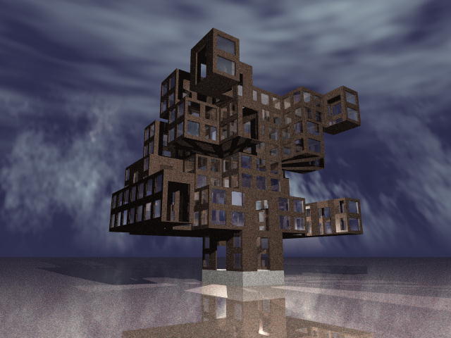
One of the first rendered, this structure shows nothing more than the chance involved in its creation—the same settings created the neat lower cube floor, while upper floors are wildly random. At this stage, the doors are open and the windows simple panes of glass.
Building #2
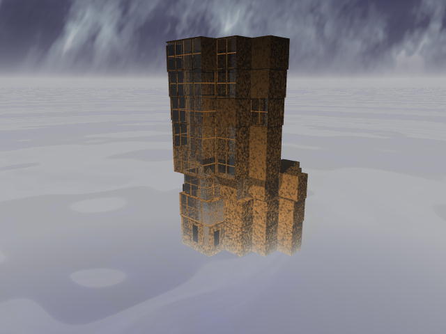
The most notable distinction with this structure is that the windows are more abundant towards the front of the structure. This was done with a gaussian module sampled with DOT so that when the dot product was 1, the probability of a windowed wall was one. The doorways on the lower floor were done the same way. Another aspect to this building is that the lower floor plans use the newFloor method, while the upper floors use distFloor with a very small dist value. This was done with a gaussian module but looks more like it could have been produced with a step.
Input
gaussian G1 {
  center dt 1
  period dt 4
  power dt 2
  sample rf DOT
}

accum A1 {
  value dt 90
  action dt 0
  factor dt 90
  probStay fn G1
  probDown dt 0.5
}

drand wl {
  min dt 20
  max dt 30
}

drand radius {
  min dt 50
  max dt 60
}

node floorPlan {
  sym_prob dt 0.5
  sym_span dt 30
  wall_length fn wl
  restoreProb dt 1.0
  alpha dt 90
  dalpha dt 90
  symSectors dt 1
  scaleX dt 1
  scaleY dt 1
  minDist dt 10
  staySame dt 0.0
  initr fn radius
}

node foundation {
  height dt 10
}

node multiFloors {
  probNextFloor dt 1.0
  maxFloor dt 8
}

node paneWindow {
  center dt 0.8
}

node distFloor {
  dist dt 1
}

node windowWall {
  xscale dt 1.0
  yscale dt 1.0
  xtrans dt 0.0
  ytrans dt 0.0
}

node paneWindow {
  sashWidth dt 0.05
  gridDivX dt 0
  gridDivY dt 0
}

step S1 {
  start dt 0.0
  stop dt 2000
  goHigh dt 0
  goLow dt 20
  sample rf Z
}

node doorAndWindowWall {
  doorProb fn G1
  winProb fn G1
  maxDoorFloor dt 1.0
}

node windowRecurse {
  winProb dt 1
  startLevel dt 1
  maxLevel dt 1
  useAspect dt 1
}

node wallSprout {
  thickness dt 2
}

gaussian G2 {
  center dt 200
  period dt 400
  power dt 0.5
  sample rf Z
}

gaussian G3 {
  center dt 0
  period dt 400
  power dt 0.5
  sample rf Z
}

node nextFloor {
  probDist fn G3
  probNew fn G2
}

node door {
  center dt 0.8
  thickness dt 0.2
}
Building #2B
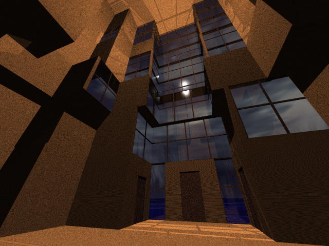
This is a view of the previous building but from an inside view. Once again, notice how the windows fade as one goes farther from the center.
Building #3
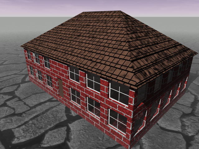
With the goal of producing the most simple, straightforward building, this was the result. It uses bilateral symmetry with 4 sectors and a long wall distance to produce the square shape, which is then scaled in the y direction by 1.5. The roof planes were used with an alpha of 35--the angle the planes are oriented off of each upper wall.
Input
gaussian G1 {
  center dt 1
  period dt 4
  power dt 2
  sample rf DOT
}

node floorPlan {
  sym_prob dt 0.0
  sym_span dt 0
  wall_length dt 50
  restoreProb dt 1.0
  alpha dt 90
  dalpha dt 90
  symSectors dt 4
  scaleX dt 1
  scaleY dt 1.5
  minDist dt 10
  staySame dt 0.0
  initr dt 50
}

node foundation {
  height dt 5
}

node multiFloors {
  probNextFloor dt 1.0
  maxFloor dt 1
}

node wallSprout {
  height dt 40
  thickness dt 2
}

node doorAndWindowWall {
  doorProb fn G1
  winProb dt 1.0
  distToWin dt 11
  maxDoorFloor dt 1.0
}

node windowWall {
  xscale dt 0.7
  yscale dt 0.7
  xtrans dt 0.0
  ytrans dt 0.0
}

node doorWall {
  height dt 20
  width dt 10
}

node door {
  center dt 0.9
  thickness dt 0.1
}

node nextFloor {
  probDist dt 1.0
  probNew dt 0.0
}

node distFloor {
  dist dt 0
}

node paneWindow {
  paneThick dt 0.2
  center dt 0.8
  sashWidth dt 0.1
  sashThick dt 0.3
  gridDivX dt 1
  gridDivY dt 1
  useAspect dt 0
  gridWidth dt 0.3
  gridThick dt 0.3
}

node roof {
  extend dt 0
  underClip dt 2
  overClip dt 0
  alpha dt 35
  flatRoof dt 0
  thickness dt 0.5
}

step S1 {
  start dt 0
  stop dt 1
  goHigh dt 0.5
  goLow dt 1
  low dt 1
  high dt 0
  sample rf DOT
}

node windowRecurse {
  winProb dt 1
  startLevel dt 1
  maxLevel dt 1
  useAspect dt 1
  divideX dt 0
  divideY dt 0
}
Building #4
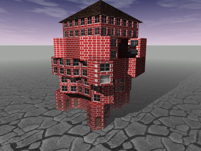
With the goal of contrasting a building sharply with the previous one, this was the result. One of the distinct things I wanted was to have a roofable upper floor (the roofing only works on convex polygonal floor plans). To do this, I used layered step functions so that their low values produce the random parameters I wanted for the lower floors and the high values produced a neat, regular upper floor. For each of the step functions, the goHigh was made so that it went high just before the upper floor.
Input
gaussian G1 {
  center dt 1
  period dt 4
  power dt 2
  sample rf DOT
}

drand R1 {
  min dt 20
  max dt 30
}

drand rProb {
  min dt 0
  max dt 1
}

drand rAngle {
  min dt 30
  max dt 90
}

drand R2 {
  min dt 40
  max dt 80
}

irand sectors {
  min dt 0
  max dt 3
}

step radius {
  start dt 0
  stop dt 500
  goHigh dt 165
  goLow dt 500
  low fn R2
  high dt 60
  sample rf Z
}

step sectors2 {
  start dt 0
  stop dt 500
  goHigh dt 165
  goLow dt 500
  low fn sectors
  high dt 4
  sample rf Z
}

step same {
  start dt 0
  stop dt 500
  goHigh dt 165
  goLow dt 500
  low fn rProb
  high dt 1.0
  sample rf Z
}

step new_wall {
  start dt 0
  stop dt 500
  goHigh dt 165
  goLow dt 500
  low fn R1
  high dt 60
  sample rf Z
}

node floorPlan {
  sym_prob dt 0
  sym_span dt 0
  wall_length fn new_wall
  restoreProb dt 0.5
  alpha dt 90
  dalpha fn rAngle
  symSectors fn sectors2
  scaleX dt 1
  scaleY dt 1
  minDist dt 4.5
  staySame fn same
  initr fn radius
  endError dt 10
}

node foundation {
  height dt 5
}

node multiFloors {
  probNextFloor dt 1.0
  maxFloor dt 5
}

node wallSprout {
  height dt 40
  thickness dt 2
}

node doorAndWindowWall {
  doorProb fn G1
  winProb fn rProb
  distToWin dt 11
  maxDoorFloor dt 1.0
}

node windowWall {
  xscale dt 0.7
  yscale dt 0.7
  xtrans dt 0
  ytrans dt 0
}

node doorWall {
  height dt 20
  width dt 10
}

node door {
  center dt 0.9
  thickness dt 0.1
}

node nextFloor {
  probDist dt 0
  probNew dt 1
}

drand R3 {
  min dt 1
  max dt 5
}

node distFloor {
  dist fn R3
}

node paneWindow {
  paneThick dt 0.2
  center dt 0.8
  sashWidth dt 0.1
  sashThick dt 0.3
  gridDivX dt 1
  gridDivY dt 1
  useAspect dt 0
  gridWidth dt 0.3
  gridThick dt 0.3
}

node roof {
  extend dt 0
  underClip dt 5
  overClip dt 0
  alpha dt 35
  flatRoof dt 0
  thickness dt 0.5
}

node windowRecurse {
  winProb dt 1
  startLevel dt 1
  maxLevel dt 1
  useAspect dt 1
  divideX dt 0
  divideY dt 0
}
Building #5
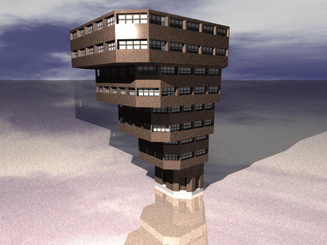
This building uses a scaled and translated gaussian to make the dist variable in the distFloor node longer towards the front of the house (using DOT as a sample).
Input
gaussian G1 {
  center dt 1
  period dt 4
  power dt 2
  sample rf DOT
}

drand R1 {
  min dt 20
  max dt 30
}

drand rProb {
  min dt 0
  max dt 1
}

drand rAngle {
  min dt 30
  max dt 90
}

drand R2 {
  min dt 40
  max dt 80
}

irand sectors {
  min dt 0
  max dt 3
}

step radius {
  start dt 0
  stop dt 500
  goHigh dt 165
  goLow dt 500
  low fn R2
  high dt 60
  sample rf Z
}

step sectors2 {
  start dt 0
  stop dt 500
  goHigh dt 165
  goLow dt 500
  low fn sectors
  high dt 4
  sample rf Z
}

step same {
  start dt 0
  stop dt 500
  goHigh dt 165
  goLow dt 500
  low fn rProb
  high dt 1.0
  sample rf Z
}

step new_wall {
  start dt 0
  stop dt 500
  goHigh dt 165
  goLow dt 500
  low fn R1
  high dt 60
  sample rf Z
}

node floorPlan {
  sym_prob dt 0
  sym_span dt 0
  wall_length fn new_wall
  restoreProb dt 0.5
  alpha dt 90
  dalpha fn rAngle
  symSectors fn sectors2
  scaleX dt 1
  scaleY dt 1
  minDist dt 4.5
  staySame fn same
  initr fn radius
  endError dt 10
}

node foundation {
  height dt 5
}

node multiFloors {
  probNextFloor dt 1.0
  maxFloor dt 5
}

node wallSprout {
  height dt 40
  thickness dt 2
}

node doorAndWindowWall {
  doorProb fn G1
  winProb fn rProb
  distToWin dt 11
  maxDoorFloor dt 1.0
}

node windowWall {
  xscale dt 0.7
  yscale dt 0.7
  xtrans dt 0
  ytrans dt 0
}

node doorWall {
  height dt 20
  width dt 10
}

node door {
  center dt 0.9
  thickness dt 0.1
}

node nextFloor {
  probDist dt 0
  probNew dt 1
}

drand R3 {
  min dt 1
  max dt 5
}

node distFloor {
  dist fn R3
}

node paneWindow {
  paneThick dt 0.2
  center dt 0.8
  sashWidth dt 0.1
  sashThick dt 0.3
  gridDivX dt 1
  gridDivY dt 1
  useAspect dt 0
  gridWidth dt 0.3
  gridThick dt 0.3
}

node roof {
  extend dt 0
  underClip dt 5
  overClip dt 0
  alpha dt 35
  flatRoof dt 0
  thickness dt 0.5
}

node windowRecurse {
  winProb dt 1
  startLevel dt 1
  maxLevel dt 1
  useAspect dt 1
  divideX dt 0
  divideY dt 0
}
Building #5B
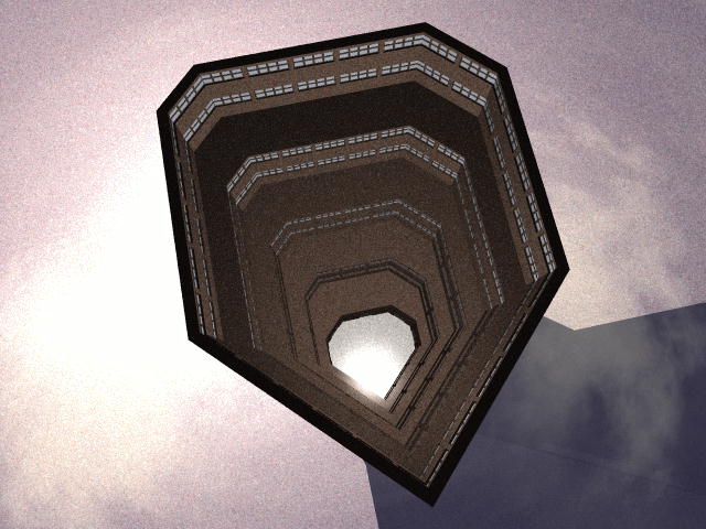
Inside view of previous building. The roof has been taken off.
Building #6
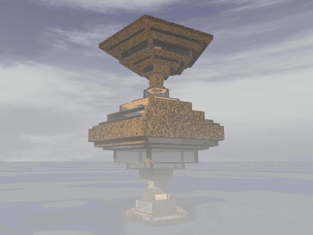
This building uses the absSin modules to vary the dist variable, the window probabilty, and each floor height.
Input
gaussian G1 {
  center dt 1
  period dt 4
  power dt 2
  sample rf DOT
}

drand R1 {
  min dt 20
  max dt 30
}

node floorPlan {
  sym_prob dt 0
  sym_span dt 0
  wall_length dt 50
  restoreProb dt 0.9
  alpha dt 90
  dalpha dt 90
  symSectors dt 5
  scaleX dt 1
  scaleY dt 1
  minDist dt 19
  staySame dt 0.5
  initr dt 50
  endError dt 1
}

node foundation {
  height dt 5
}

node multiFloors {
  probNextFloor dt 1.0
  maxFloor dt 25
}

absSin Sin1 {
  start dt 0
  stop dt 80
  scale dt 20
  trans dt 5
  sample rf Z
}

node wallSprout {
  height fn Sin1
  thickness dt 5
}

gaussian G2 {
  center dt 0
  period dt 100
  power dt 1
  sample rf Z
}

node doorAndWindowWall {
  doorProb fn G1
  winProb fn G2
  distToWin dt 11
  maxDoorFloor dt 1.0
}

node windowWall {
  xscale dt 0.9
  yscale dt 0.9
  xtrans dt 0
  ytrans dt 0
}

node doorWall {
  height dt 5
  width dt 10
}

node door {
  center dt 0.9
  thickness dt 0.1
}

 nextFloor {
  probDist dt 1
  probNew dt 0
}

absSin Sin2 {
  start dt 0
  stop dt 400
  scale dt 40
  trans dt -20
  sample rf Z
}

node distFloor {
  dist fn Sin2
}

node paneWindow {
  paneThick dt 0.2
  center dt 0.0
  sashWidth dt 0.005
  sashThick dt 0.4
  gridDivX dt 0
  gridDivY dt 0
  useAspect dt 0
  gridWidth dt 1
  gridThick dt 0.5
}

node roof {
  extend dt 0
  underClip dt 5
  overClip dt 0
  alpha dt 35
  flatRoof dt 1
  thickness dt 0.5
}

node windowRecurse {
  winProb dt 1
  startLevel dt 0
  maxLevel dt 0
  useAspect dt 1
  divideX dt 0
  divideY dt 0
}
Buildings #1
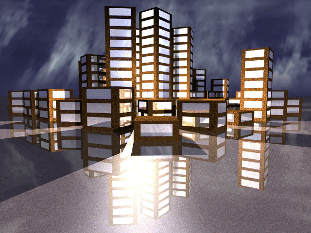
The crown jewel of images, this shows how multiple buildings can be combined and varied over distance. To do this, I created the GX, GY, and GZ position variables to represent the 'world' coordinates of each house. I then created two gaussian functions varying in the x and y direction. The average module was created in order to average these functions. The resulting probabilty was used as a value for probNextFloor in node multiFloors so that buildings in the center created more floors. This effect mimics a city center surrounded by outlying, smaller buildings.
Input
gaussian G1 {
  center dt 1
  period dt 4
  power dt 2
  sample rf DOT
}

drand R1 {
  min dt 20
  max dt 30
}

node floorPlan {
  sym_prob dt 0
  sym_span dt 0
  wall_length dt 60
  restoreProb dt 0.9
  alpha dt 90
  dalpha dt 90
  symSectors dt 2
  scaleX dt 1
  scaleY dt 1
  minDist dt 19
  staySame dt 0.5
  initr dt 50
  endError dt 1
}

node foundation {
  height dt 5
}

gaussian xProb {
  center dt 0
  power dt 0.5
  period dt 1200
  sample rf GX
  scale dt 0.9
}

gaussian yProb {
  center dt 0
  power dt 0.5
  period dt 1200
  sample rf GY
  scale dt 0.9
}

average totalProb {
  d1 fn xProb
  d2 fn yProb
}

node multiFloors {
  probNextFloor fn totalProb
  maxFloor dt 15
}

node wallSprout {
  height dt 40
  thickness dt 5
}

node doorAndWindowWall {
  doorProb fn G1
  winProb dt 1.0
  distToWin dt 11
  maxDoorFloor dt 1.0
}

node windowWall {
  xscale dt 0.7
  yscale dt 0.7
  xtrans dt 0
  ytrans dt 0
}

node doorWall {
  height dt 5
  width dt 10
}

node door {
  center dt 0.9
  thickness dt 0.1
}

node nextFloor {
  probDist dt 1
  probNew dt 0
}

node distFloor {
  dist dt 0
}

node paneWindow {
  paneThick dt 0.2
  center dt 0.0
  sashWidth dt 0.005
  sashThick dt 0.4
  gridDivX dt 0
  gridDivY dt 0
  useAspect dt 0
  gridWidth dt 1
  gridThick dt 0.5
}

node roof {
  extend dt 0
  underClip dt 5
  overClip dt 0
  alpha dt 35
  flatRoof dt 1
  thickness dt 0.5
}

node windowRecurse {
  winProb dt 1
  startLevel dt 0
  maxLevel dt 0
  useAspect dt 1
  divideX dt 0
  divideY dt 0
}
Final Report
Ryan Robbins
Project For CS-433
University of Utah
June 2, 1996
Project Overview
The goal of this project was to create and implement a method for modeling buildings in a way that removes the endless details such modeling entails. The central theme to was give the modeller the ability to create the most chaotic or the most controlled of structures, requiring little user input. Eventually, to be able to create buildings narrow enough to fit within a precise historical style and broad enough to fit in the context of science fiction. For that reason, you'll see that most of my methods aim at being as structurally diverse as possible, while not relinquishing the ability to be controlled.
Input Output
The direct input to the program is a bounding square centered around the origin and a direction that identifies the "front" of the structure. The only guarantee the program makes concerning the bounding square is that the building will not go out of bounds on the lower floor. Depending on certain parameters, the building can go anywhere it wants after the first floor. The front vector does nothing more than provide a mathematical framework for the modules described in the next section.
Control Modules
Essential to this project was the notion of control. Is the placement of objects based on constants, random numbers, mathematical formulas, or all of the above? The answer I chose was all of the above. It's whatever the programmer can think up. This notion is embodied in the classes functor and dsource. Class functor, as the name implies, represents any functional unit. Class dsource can represents a constant, a function, or a reference to a global geometric variable. By making the control data for functors dsources themselves, one can layer functions within functions to get a wide variety of effects.
These geometric variables, namely X, Y, Z, LOCX, LOCY, LOCZ, and DOT, are what provide the original input to the functions that need them. Specific nodes will set these variables accordingly and any data sources that use these variables will change along with them. X, Y, and Z are intended for global space while their LOC (local) counterparts are meant to be specific to the local space of an object. DOT is the normalized dot product of the center vector with the vector formed by X and Y.
Building Trees
One of the key elements of this structural design was that the components of the building are created in independent methods called (who would of guessed) nodes. Therefore, each element of construction is inherited from the class node. Each node has a linked list of children nodes and supports a variety of placement procedures. To provide more control over these nodes each has a pointer to class house.
Class house is used as both an interface to the nodes and as a retainer for data intended to be global to all nodes. An example of this is the linked list of lines that comprises the floor plan. So many nodes use this data that it would be unwieldy to pass it all around through parameters.
Floor Plan
The node floorPlan was indeed the most difficult component of this program. The floor plan (if I can indeed call it that) is generated independently of any notion of internal structure. The form does not follow function, it follows whim. Essentially this boils down to the creation of a polygon, yet its construction and control is by no means simple and presented both a programming and conceptual challenge.
As always, my main goal was to develop a model that could provide high diversity and yet reduce to the common case. Looking into L-systems and Lindenmayer grammars I found high diversity but little control. Perhaps I didn't look too deeply (the subject would have made a fine project in and of itself) but I could not think of a dependable way to control a structure based on a rewriting system. So I chose a method similar but more straightforward.
The polygon is controlled in same way, with a "turtle" as in turtle graphics. The turtle moves a given distance at a given angle, controlled by class turtleControl. The turtle can be started at angle alpha and point (x,y) and then proceeds in a counter-clockwise direction each time its getLines function is called.
The idea behind this control is that the function getLines returns three different lines, or directions, that the turtle can follow based on dsource variables defining the differential angle and distance. The user program (in this case the floorPlan node) can then analyze these lines and choose which one it wants with the choose function. The control returns the lines in a prioritized order based on how far away the line is from the "steady state". The "steady state" is defined to be the direction perpendicular to the vector formed by the current point (x,y). If the differential angle is small enough and the control always chooses to go towards the steady state, the result would be a fine polygon—or if carried to the extreme, a circle. The motivation behind this model is to make sure the floor stays close to the ideal closed path.
In more detail, the turtleControl first tests a dsource variable for a probability of the turtle staying in the same direction. If true, this direction gets first priority, otherwise last. To prioritize the other directions, the dot product of the current direction vector and the "steady state" vector is used as input to a dsource variable function range(sample). The return result is used as a probability of going in the direction that goes towards the "steady state" direction.
Node floorPlan then tests all three lines for possible conflicts. There are several factors that can invalidate a line: intersection with another line, intersection with the bounding square, or being too close to another line. A variable minDist defines the minimum distance two lines can be from each other. The key problem with this is that all three lines may be invalid. To overcome this, each time a choice is made to follow a given direction, the state of the turtle is pushed onto a stack. Whenever we reach a dead-end, we backtrack to a previous state and continue.
One of the main limitations of floorPlan at the moment is that it pretty much requires a sector symmetry to get dependable results. By sector symmetry I mean that the unit circle is divided into sectors of equal span and everything is symmetrical within those sectors. I meant to make much more of symmetry but time simply ran out. See the symmetry discussion later on.
Walls
Node floorPlan continues onward by calling a foundation procedure—a simple prism in POV-ray—and then building walls on top with node wallSprout. Node wallSprout does the key clipping involved in making connecting walls—clipping along the bisecting angle formed by the two walls. WallSprout calls its children with the assumption that they return their cut-out object (CSG object to cut out windows and doors etc.) via the return parameter and their actual object via the object rtn located in the class house. WallSprout then combines all cut-out components and cuts them out of rtn.
For now, walls are simple cubes with control parameters for width, height, and thickness. More complex walls, such as tiled bricks or boards, could ( with a little more time) be easily constructed.
Doors
The model for doors is perhaps the simplest. The door is always centered along the wall with parameters for width, height, and thickness. The key to the doors is the member center. It is expected that center be from 0 to 1 and defines the percentage of the wall thickness to use as a distance from the front of the wall to the center of the door. The same model is used for windows.
The other thing to note about doors is their relation to node doorAndWindowWall. If a door is chosen based on probability variables, it is modeled the same as always. Following that, windows can be created on both sides of the door using the window placement node. This stage of creation takes place in doorAndWindowWall.
Extensions such as arched doors, double doors, and doors spaced along one wall are obvious choices for furthering this node.
Windows
The placement of windows on a given wall is done recursively. The bare wall is defined to be level 0 and further levels of subdivision increase the level. At each level, the level value is used as input to a variable function which then returns a probability of forming a window. If the test succeeds, a window is created through children procedures and subdivision halts at that level. Otherwise subdivision continues based on certain control variables.
These variables can determine the dimensions of the subdivision—i.e. aspect ratio, x divisions, y divisions. Also, certain constraints such as minLevel and maxLevel help constrain the span in which a window can be placed. With a high min and max level and a window probability of 1, the windows would be small and tightly spaced along a wall.
The children of this node (called windowRecurse), also give more flexibility to the placement of windows. The node windowWall, gives the option of scaling and translating after placement. The node paneWindow, which produces grids, slips (which hold windows together and forms window outline), and actual glass pane, gives options for thickness and centering.
The nature of this recursive placement scheme is a fine example of what I was looking for in all methods—a method with the potential for diverse and random behavior but with simple controls that limit it to a normal case. For windows with a minLevel of 0 and a winProb (window probability) of 1 there will always be only one window for that given wall.
Ornament
Ornament exists in such a wide array as to make serious support for such diversity nearly impossible. I had intended as part of this project to generalize ornament types, categorizing them by their physical relations with more fundamental components—so that a door might have placement nodes that place objects along the casing or cut patterns out of the surface.
The key to attaining the necessary diversity with this method is to let the user define objects outside of the program and use them for placement in a relational way. The user could have statues instead of columns supporting a balcony, could have an intricately carved door instead of a simple cube, or could have human forms as bricks that form the walls.
The key to doing this (it is not implemented now) is to give each of the node's children an index that identifies it as either a method or an object. At the moment, a call to a node's placement procedures is done with a choose() or choose(int) function. Without the int, choose uses the functor decide to choose an index, otherwise the int specifies a physical index into the linked list of children nodes. By making the index "virtual"—by no longer associating it with a physical place in the linked list—the user would be able to define the functor decide to access desired ranges for that node.
This is the main method I intended for gaining program support for specific styles. For all nodes that do nothing more than place an object with a given geometrical specification, the user could define an array of objects that could be used in place of the default and define the way that objects is chosen.
The Next Floor
There are two ways to proceed to the next floor. One is to simply construct a new floor in the same way as the first. The second is to take the original floor plan and extend. The way I have chosen for extending is to take each wall and give it overhang or underhang—that is, each line in the house floor plan is duplicated a given distance away from its original position. The distance can be positive for overhang and negative for underhang and the new line will always be parallel to the old. Starting with a square floor plan, consistent underhang will produce a pyramid.
This stage also requires that we form the "underside" of the overhang. For underhang, we can make the new area either in the same way or (if it were done) pass that area onto the roofing mechanism (see the discussion on roofing). To do the former method, we make use of the prism created for the previous floor translating it up to the new height and cutting the new prism away. Also, by cutting the old away from the new, the inside of the house is removed of all floors. A more internally oriented method could keep the floors and cut away openings for stairs.
Roofing
By far one of the most difficult aspects of this project is the roofing. The direct manifestations of this is that most all of the structures shown have flat roofs. In other words, I never came up with a general way to roof all the diverse floor plans that could be created. The only sloped roofing you'll see is done on a simple convex floor, which I'll talk about shortly. I did give roofing a lot of thought though, and will discuss two general approaches that might be taken.
First is to define the roof by the shape and height of its ridge. One could let a turtle loose within the roofing area to create the shape of the ridge and let the user define the height. The program then attaches polygons from the roofing area to the ridge. One might also extend the ridge to form a polygon instead of a line, where the polygon becomes another roofing area and the roof is created recursively. With this method, if the second roofing polygon is made near flat, such things as mansard roofs could be created. The most difficult aspect of this approach is figuring how to give the user control over the formation of the ridge and the attachment of the roofing polygons. While this approach might be easier to implement, it doesn't leave much in the way of directly controlling the physical style of roofing.
The second approach is to let the user define the outside edges of the roofing area as either a gable or a sloping plane. Once all the edges are formed, the resulting planes are clipped against each other and the roof ridge forms by itself as a result of the clipping. The difficulty with this is choosing which planes are clipped against each other. With a convex roofing area, the answer is to clip each plane against every other plane. For single, non-gable planed roofing, this is what I have implemented for my program. To create roof overhang, all one has to do is clip the planes below the upper edge of the walls.
Symmetry Problem
One of the glaring omissions from my symmetry is that it does not extend into all components of the house. To remedy this, the floor plan could, instead of creating simple lines, overload the lines with information about symmetry and specific orientation. Then, when the walls are created, a module like wallSprout that oversees much of a floor's creation can control how tightly the symmetry is obeyed. If the proper orientation of the line is maintained (its front and direction), little change would be necessary to the component modules further down in the building trees. To control the randomness, the dsource class could be controlled to return the same value a given amount of times. This control could be dictated by a module like wallSprout.
Integrating Internal Structure
If I could rework the whole project again, I would try to integrate the internal and external structure of the house into the floor plan creation. Instead of creating simple lines, decisions about how those lines relate to the structure would be made and retained for further processing. One might, for every wall, distinguish either a hallway or a room on the other side. The hallway could be running parallel or perpendicular (for doors) to the wall. These decisions could influence the shape and direction of walls to follow. In this way, the diversity gained by a polygonal method might still be maintained.
Another way might be to let the turtle create one room at a time. Each wall of the room might open up into another room, a perpendicular or parallel hallway, or the outside of the house. Integrating adjoining walls with each other would probably be the main challenge here.
Varying Shapes
The support of a wider variety of shapes could greatly increase the diversity of a structure. With walls, windows, and roofing made from splines, the results could be truly bizarre. A simple next step, though, would be to create cylindrical sections of walls for spires.
Conclusion
Over all, I feel I have been generally successful in formulating a base from which to build on in the construction of computer generated architecture. As I knew from the start, I would never succeed in "finishing" this program. My main goal was to create a framework that touched on all the central ideas and could be easily extended with more time. Indeed, much of what is left (aside perhaps from the roofing) is the generation of modeling details. Like the windows and floor plan, these details can be integrated in the program with a complex placement method or simply defined by the user and placed where appropriate.
